Chapter 16
Input/Output
In this chapter we discuss the I/O subsystem. The I/O subsystem is the means by which the CPU
communicates with the outside world. By “outside world” we mean devices other than the CPU and
memory.
As you have learned, the CPU executes instructions, and memory provides a place to store data and
instructions. Most programs read data from one or more input devices, process the data, then write the
results to one or more output devices.
Typical input devices are keyboards and mice. Common output devices are display screens and printers.
Although most people do not think of them as such, magnetic disks, CD drives, etc. are considered as
I/O devices. It may be a little more obvious that a connection with the internet is also seen as
I/O. The reasons will become clearer in this chapter, where we discuss how I/O devices are
programmed.
16.1 Memory Timing
Since the CPU accesses I/O devices via the same buses as memory (see Figure 1.1, page 9), it might seem
that the CPU could access the I/O devices in the same way as memory. That is, it might seem that I/O
could be performed by using the movb instruction to transfer bytes of data between the CPU and the specific
I/O device. This can be done with many devices, but there are other issues that must be taken into
account in order to make it work correctly. One of the main issues lies in the timing differences
between memory and I/O. Before tackling the I/O timing issues, let us consider memory timing
characteristics.
Aside: As pointed out in Section
1.2 (page
10), the three-bus description given here shows the
logical interaction between the CPU and I/O. Most modern general purpose computers employ
several types of buses. The way in which the CPU connects to the various buses is handled by
hardware controllers. A programmer generally deals only with the logical view.
Two types of RAM are commonly used in PCs.
- SRAM holds its values as long as power is on. Access times are very fast. It requires more
components to do this, so it is more expensive and larger.
- DRAM uses passive components that hold data values for only a few fractions of a second.
Thus DRAM includes circuitry that automatically refreshes the data values before the values
are completely lost. It is much less expensive than SRAM, but also much slower.
Most of the memory in a PC is DRAM because it is much less expensive and smaller than SRAM. Of course,
each instruction must be fetched from memory, so slow memory access would limit CPU speed. This problem
is solved by using cache systems made from SRAM.
A cache is a small amount of fast memory placed between the CPU and main memory. When the CPU
needs to access a byte in main memory, that byte, together with several surrounding bytes, are copied into
the cache memory. There is a high probability that the surrounding bytes will be accessed soon, and the
CPU can work with the values in the much faster cache. This is handled by the system hardware. See [28]
and [31] for more details.
Modern CPUs include cache memory on the same chip, which can be accessed at CPU speeds. Even
small cache systems are very effective in speeding up memory access. For example, the CPU in my desktop
system (built in 2005) has 64 KB of Level 1 instruction cache, 64 KB of Level 1 data cache, and 512 KB of
Level 2 cache (both instructions and data). In contrast, most of the memory in the system consists of 1 GB
of DDR 400 memory.
The important point here is that memory is matched to the CPU by the hardware. Very seldom is
memory access speed a programming issue.
Aside: There are some cases where knowing how to manipulate memory caches can speed up
execution time. The x86 has instructions for working directly with cache. Optimizing cache
usage is an advanced topic beyond the scope of this book.
16.2 I/O Device Timing
I/O devices are much slower than memory. Consider a common input device, the keyboard. Typing at 120
words per minute is equivalent to 10 characters per second, or 100 milliseconds between each character. A
CPU running at 2 GHz can execute approximately 200 million instructions during that time. And
the time intervals between keystrokes are very inconsistent. Many will be much longer than
this.
Even a magnetic disk is very slow compared to memory. What if the byte that needs to be read has just
passed under the read/write head on a disk that is rotating at 7200 RPM? The system must wait for a full
revolution of the disk, which takes 8.33 milliseconds. Again, there is a great deal of variability in the
rotational delay between reads from the disk.
In addition to being much slower, I/O devices exhibit much more variance in their timing. Some people
type very fast on a keyboard, some very slow. The required byte on a magnetic disk might be just coming up
to the read/right head, or it may have just passed. We need a mechanism to determine whether an input
device has a byte ready for our program to read, and whether an output device is ready to accept a byte
that is sent to it.
16.3 Bus Timing
Thus far in this book buses have been shown simply as wires connecting the subsystems. Since more than
one device is connected to the same wires, the devices must follow a protocol for deciding which two devices
can use the bus at any given time. There are many protocols in use, which fall into one of two
types:
-
Synchronous
- — data transfer is controlled by a clock signal. Typically, a centralized bus controller
generates the clock signal, which is sent on a separate control line in the bus.
-
Asynchronous
- — data transfer is controlled by a “handshaking” exchange between the two devices.
Many asynchronous protocols are handled by the devices themselves over the data and address
lines in the bus.
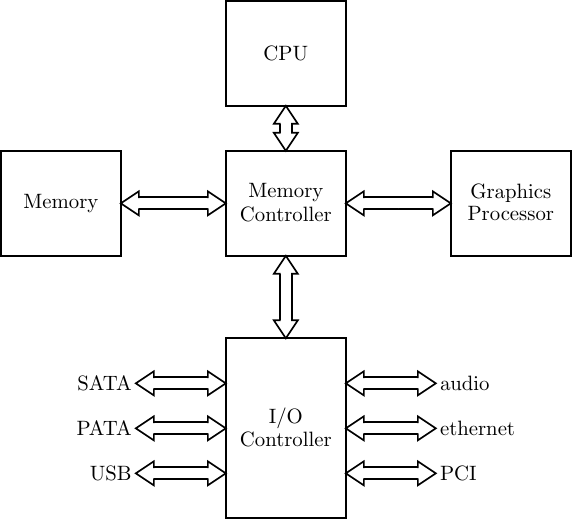
Modern computer systems employ both types of buses. A typical PC arrangement is shown in Figure
16.1.
16.4 I/O Interfacing
In addition to a very wide range in their timing, there is an enormous range of I/O devices that are
commonly attached to computers, which differ greatly in how they handle data. A mouse provides position
information. A monitor displays graphic information. Most computers have speakers connected to them.
Ultimately, the CPU must be able to communicate with I/O devices in bit patterns at the speed of the
device.
The hardware between the CPU and the actual I/O device consists of two subsystems — the controller
and the interface. The controller is the portion that works directly with the device. For example, a keyboard
controller detects which keys are pressed and converts this to a code. It also detects whether a key is pressed
or not. A disk controller moves the read/write head to the requested track. It then detects the sector number
and waits until the requested sector comes into position. Some very simple devices do not need a
controller.
The interface subsystem provides registers that the CPU can read from or write to. An I/O device
is programmed through the interface registers. In general, the following types of registers are
provided:
- Transmit — Allows data to be written to an output device.
- Receive — Allows data to be read from an input device.
- Status — Provides information about the current state of the device, including the controller.
- Control — Allows a program to send commands to the controller and to change its settings.
It is common for one register to provide multiple functionality. For example, there may be one register for
transmitting and receiving, its functionality depending on whether the CPU writes to or reads from the
register. And it is common for an interface to have more than one register of the same type, especially
control registers.
16.5 I/O Ports
The CPU communicates with an I/O device through I/O ports. The specific port is specified by a value on
the address bus. There are two ways to distinguish an I/O port address from a physical memory
address:
- Isolated I/O
- Memory-Mapped I/O
With isolated I/O, the I/O ports can be numbered from 0x0000 to 0xffff. This address space is
separate from the physical memory address space. Instructions are provided for accessing the
I/O address space. The distinction between the two addressing spaces is made in the control
bus.
One instruction to perform input is:
where s denotes the size of the operand:
| s | meaning | number of bits |
| b | byte | 8 |
| w | word | 16 |
| l | longword | 32 |
| q | quadword | 64 |
| |
| Intel® Syntax | | in | destination, source |
| |
The in instruction moves data from the I/O port specified by the source into the register specified by the
destination. The source operand can be either an immediate value, or a value in the dx register. The
destination must be al, ax, or eax, consistent with the operand size. For example, the instruction
reads I/O port number 4, placing the value in the al register.
An instruction to perform output is:
where s denotes the size of the operand:
| s | meaning | number of bits |
| b | byte | 8 |
| w | word | 16 |
| l | longword | 32 |
| q | quadword | 64 |
| |
| Intel® Syntax | | out | destination, source |
| |
The out instruction moves data to the I/O port specified by the destination from the register specified by
the source. The destination operand can be either an immediate value, or a value in the dx register. The
source must be al, ax, or eax, consistent with the operand size. For example, the instruction
writes the value in the al register to I/O port number 6.
16.6 Programming Issues
One of the primary jobs of an operating system is to handle I/O. The software that does this is called a
device handler. The operating system coordinates the activities of all the device handlers so that the
hardware is utilized in an efficient manner. In Linux, a device handler may either be compiled into the kernel
or in a separate module that is loaded into memory only if needed.
Thus, programming I/O devices generally means changing the operating system kernel. This can be done,
but it requires considerably more knowledge than is provided in this book. It is possible to give user
applications permission to directly access specific I/O devices, but this can produce disastrous results,
especially in a multi-user environment.
We will not do any direct I/O programming in this book, but we will look at the general concepts.
Listing 16.1 sketches the general algorithms in C. The code was abstracted from some I/O routines that
work with a Dual Asynchronous Universal Receiver/Transmitter (DUART) on a single board computer.
It is incomplete code and does not run on any known computer, but it illustrates the basic
concepts.
This example uses memory-mapped I/O. The program calls three functions:
- init io — Initialize the I/O interface. This includes placing the hardware in an “all clear”
state and setting parameters such as speed, etc.
- charin — Read one character from the input.
- charout — Write one character to the output.
We will examine what each does.
Lines 12 – 37 define symbolic names for values that are used to program the device. Notice that some
names have the same value. For example, on lines 17 and 18 the receiver register (RR) and transmitter
register (TR) are actually the same register. The CPU receives when it reads from this register and transmits
when it writes to it. A similar situation is seen on lines 14 and 15. Reading from register 0x03 provides
status information, and the clock selection commands are written to the same register. This illustrates an
important point — I/O interface registers are not simply data storage places like CPU registers. It would
probably be more accurate to call them “interface ports,” but “registers” is the commonly used
terminology.
This example uses memory-mapped I/O, so simple assignment statements are used to access the
I/O interface registers. The memory addresses 0xff000 – 0xff020 are associated with I/O
registers for this device instead of physical memory. The base address of the device is assigned
to a pointer variable on line 54 in the init io function. Then the commands to initialize the
device are written to the appropriate registers on lines 56 – 66. It is not important that you
completely understand what this function is doing, but the comments should give you a rough
idea.
Lines 56 – 59 assign four different values to the same location:
*(port+CR) = RESETRECEIVER; /* reset receiver */ *(port+CR) = RESETTRANSMIT; /* reset transmitter */ *(port+CR) = RESETERROR; /* clear any errors */ *(port+CR) = RESETMODE; /* make sure we’re using MR1 */
If these were assignment to an actual memory location or to a CPU register, only the final statement
would be required. But the Command Register is an I/O interface register. And as described above, it really
is not a storage register, even on the I/O interface. In fact, these are four different commands that are sent
to the Command Register “port” on the I/O interface.
The order in which commands are sent to the I/O interface may also be important. For example, on this
particular device, the sequence on lines 62 – 63
*(port+MR) = NOPARITY8BITS; /* no parity, 8 bits */ *(port+MR) = STOPBIT2; /* stop bit length 2.000 */
must be performed in this order. There are actually two Mode Registers, which are both accessed
through the same I/O interface register. The first time the register is accessed, it is connected to Mode
Register 1. This access causes the hardware to automatically switch to Mode Register 2 for all subsequent
accesses. Now you can understand the reason for sending the “RESETMODE” command to the
Command Register on line 59. It’s important to ensure that the first access will be to Mode Register
1.
When compiling I/O functions, it is very important not to use optimization. If you do, the compiler may
try coalesce command values into one value. (See Exercise 1.)
The next function is charin(). Its job is to read a character from the DUART. In the lab where this
code was used, the DUART receiver was connected to a keyboard. The DUART must wait until somebody
presses a key on the keyboard, then convert the code for that key to an eight-bit ASCII code representing
the character. When the DUART has a character ready to be read from its receiver register, it sets the
“receiver ready” bit in its status register to one. The do-while loop on lines 73 – 76 in charin show how the
code must wait for this event.
When the status indicates that a character is ready, line 77 shows how it is read from the receiver
register.
The charout() function writes a character to the transmitter. As you might expect, the transmitter was
connected to a computer monitor. Although it is clear that keyboard input is very slow, writing on a monitor
screen is also slow compared to CPU processing. Thus, we need a similar do-while loop (lines 83 – 88) to
wait until the monitor is ready to accept a new character. Once the value provided by the status
register shows it is ready, line 89 shows how the character is written to the DUART’s transmitter
register.
Listing 16.2 shows the assembly language generated by the gcc compiler for the C program in Listing
16.1. Some comments have been added to explain the general concepts.
The comments on line 26 – 41 in the init_io function describe how values are written to the appropriate
memory addresses, which are mapped to I/O registers.
Lines 66 – 73 in the charin function make up a loop that waits until the receiver has a character ready
to be read. The readiness of the receiver is indicated by bit 2 in the status register. The character is read
from that register on line 75. A similar loop is used on lines 89 – 96 in the charout function to wait
until the status register shows that the transmitter is ready for another character. When it is
ready, the address of the transmitter register is computed on lines 97 – 98, the byte to be sent
is loaded into the eax register on line 99, and it is written to the transmitter register on line
100.
As we saw in Section 16.5, special instructions are required to access isolated I/O. The Linux kernel
source includes macros to use these instructions. The macros are defined in the file io.h. Listing 16.3
illustrates the use of these macros to write the same program as in Listing 16.1 if the DUART interface were
connected to the isolated I/O system.
On line 11 we need to include the file containing the macros:
The use of the outb() macro can be seen in lines 56 – 65. And on line 75 we see the inb() macro being
used to read the status register.
The gcc compiler generates assembly language as shown in Listing 16.4
Looking at lines 3 – 24 and lines 25 – 42, we see that the inb() and outb() macros generate functions. The
actual inb instruction is used on line 15 and outb is used on line 37.
At the points where the macros are called in the C source code, the compiler generates calls to the
appropriate function. For example, the C sequence
56 outb(CR, RESETRECEIVER); 57 outb(CR, RESETTRANSMIT);
generates the assembly language (comments added)
66 movl $32, %esi 67 movl $5, %edi 68 call outb # outb(CR, RESETRECEIVER); 69 movl $48, %esi 70 movl $5, %edi 71 call outb # outb(CR, RESETTRANSMIT);
16.7 Interrupt-Driven I/O
Reading the code in Section 16.6, you probably realize that the CPU can waste a lot of time simply waiting
for I/O devices. Most I/O interfaces include hardware that can send an interrupt signal to the CPU when
they have data ready for input or are able to accept output (see Section 15.1, page 871). While waiting for
an I/O device, the operating system will suspend the requesting process and allow another process, perhaps
being run by another user, to use the CPU.
The device handler for each I/O device that can interrupt includes a special interrupt handler function.
The address of each interrupt handler is stored in a table in the operating system. When the requested I/O
device is ready for I/O, it sends an interrupt signal to the CPU on the control bus. The device identifies
itself to the CPU, and the CPU consults the table to obtain the address of the corresponding interrupt
handler. CPU execution control then transfers to the interrupt handler function, which contains code to
read from or write to the device as needed. When the interrupt handler function completes its
servicing of the I/O device, the last instruction in the function is an iret (see Section 15.5
on page 875). This causes CPU execution control to return to the control flow where it was
interrupted.
This is a highly simplified description. The operating system must perform a great deal of “bookkeeping”
in this transfer of control. For example, before allowing the interrupt handler function to execute, at
least any registers that will be used in the function must be saved. And more than one process
may be waiting for I/O to complete. The operating system must keep track of which process is
waiting for which I/O device and make sure that the process gets or sends the correct input or
output.
Many other issues face the device handler programmer. For example, I/O devices are left to run on their
own time, so one device may attempt to interrupt while another device’s interrupt handling function is
being executed. The programmer must decide whether the interrupt should be allowed or not.
In general, it cannot be ignored because this would cause the loss of I/O data. On the other
hand, spending too much time handling the second interrupt may cause the first device to lose
data.
16.8 I/O Instructions
| opcode | source | destination | page |
|
|
|
|
| ins | $imm/%reg | %reg/mem | 890 |
|
|
|
|
| outs | $imm/%reg | %reg/mem | 891 |
|
|
|
|
|
|
|
|
| s = b, w, l, q
|
| |
16.9 Exercises
-
16-1
-
(§16.6) Enter the C program in Listing 16.1. Compile it to the assembly language stage (use
the -S option) with different levels of optimization. For example, -O1, -O2. Compare the results
with the non-optimized version in Listing 16.2.
-
16-2
-
(§16.6) Enter the C program in Listing 16.3. Compile it to the assembly language stage (use
the -S option) with different levels of optimization. For example, -O1, -O2. Compare the results
with the non-optimized version in Listing 16.4.