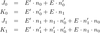
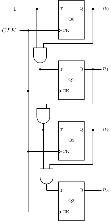
four
Store a digit in every four bits. Thus, the lowest-order digit would be stored in bits 7 – 0, the next lowest-order in 15 – 8, etc., with the highest-order digit in bits 31 – 24.
No, binary addition does not work. For example, let’s consider 48 + 27:

See next answer.
No, it doesn’t work. The problem is that the range of 4-bit signed numbers in two’s complement format is −8 ≤ x ≤ +7, and (+4) + (+5) exceeds this range.

No, it doesn’t work. The problem is that the range of 4-bit signed numbers in two’s complement format is −8 ≤ x ≤ +7, and (−4) + (−5) exceeds this range.

Adding any number to its negative will set the CF to one and the OF to zero. The sum is 2n, where n is the number of bits used for representing the signed integer. That is, the sum is one followed by n zeroes. The one gets recorded in the CF. Since the CF is irrelevant in two’s complement arithmetic, the result — n zeroes — is correct.
In two’s complement, zero does not have a representation of opposite sign. (-0.0 does exist in IEEE 754 floating point.) Also, −2n−1 does not have a representation of opposite sign.
a) +85 b) -86 c) -16 d) +15 e) -128 f) +99 g) +123
a) +4660 b) -4660 c) -292 d) +2000 e) -32768 f) +1024 g) -1 h) +30767
a) 64 b) ff c) f6 d) 58 e) 7f f) f0 g) e0 h) 80
CF = 0 ⇒ unsigned right
OF = 0 ⇒ signed right b) 45
CF = 1 ⇒ unsigned wrong
OF = 0 ⇒ signed right c) fb
CF = 0 ⇒ unsigned right
OF = 0 ⇒ signed right d) de
CF = 0 ⇒ unsigned right
OF = 1 ⇒ signed wrong e) 0e
CF = 1 ⇒ unsigned wrong
OF = 0 ⇒ signed right f) 00
CF = 1 ⇒ unsigned wrong
OF = 1 ⇒ signed wrong
CF = 1 ⇒ unsigned wrong
OF = 0 ⇒ signed right b) 1110
CF = 1 ⇒ unsigned wrong
OF = 0 ⇒ signed right c) 0000
CF = 1 ⇒ unsigned wrong
OF = 1 ⇒ signed wrong d) 03ff
CF = 1 ⇒ unsigned wrong
OF = 0 ⇒ signed right e) 7fff
CF = 0 ⇒ unsigned right
OF = 0 ⇒ signed right f) 7fff
CF = 1 ⇒ unsigned wrong
OF = 1 ⇒ signed wrong
1/*
2 * hexTimesTen.c
3 * Multiplies a hex number by 10.
4 * Bob Plantz - 19 June 2009
5 */
6
7#include "readLn.h"
8#include "writeStr.h"
9#include "hex2int.h"
10#include "int2hex.h"
11
12int main(void)
13{
14 char aString[9];
15 unsigned int x;
16
17 writeStr("Enter a hex number: ");
18 readLn(aString, 9);
19 x = hex2int(aString);
20 x *= 10;
21 int2hex(aString, x);
22 writeStr("Multiplying by ten gives: ");
23 writeStr(aString);
24 writeStr("\n");
25
26 return 0;
27}
1/*
2 * hex2int.h
3 *
4 * Converts a hexadecimal text string to corresponding
5 * unsigned int format.
6 * Assumes text string is valid hex chars.
7 *
8 * input:
9 * pointer to null-terminated text string
10 * output:
11 * returns the unsigned int.
12 *
13 * Bob Plantz - 19 June 2009
14 */
15
16#ifndef HEX2INT_H
17#define HEX2INT_H
18
19unsigned int hex2int(char *hexString);
20
21#endif
1/*
2 * hex2int.c
3 *
4 * Converts a hexadecimal text string to corresponding
5 * unsigned int format.
6 * Assumes text string is valid hex chars.
7 *
8 * input:
9 * pointer to null-terminated text string
10 * output:
11 * returns the unsigned int.
12 *
13 * Bob Plantz - 19 June 2009
14 */
15
16#include "hex2int.h"
17
18unsigned int hex2int(char *hexString)
19{
20 unsigned int x;
21 unsigned char aChar;
22
23 x = 0; // initialize result
24 while (*hexString != ’\0’) // end of string?
25 {
26 x = x << 4; // make room for next four bits
27 aChar = *hexString;
28 if (aChar <= ’9’)
29 x = x + (aChar & 0x0f);
30 else
31 {
32 aChar = aChar & 0x0f;
33 aChar = aChar + 9;
34 x = x + aChar;
35 }
36 hexString++;
37 }
38
39 return x;
40}
1/*
2 * int2hex.h
3 *
4 * Converts an unsigned int to corresponding
5 * hex text string format.
6 * Assumes char array is big enough.
7 *
8 * input:
9 * unsigned int
10 * output:
11 * null-terminated text string
12 *
13 * Bob Plantz - 19 June 2009
14 */
15
16#ifndef INT2HEX_H
17#define INT2HEX_H
18
19void int2hex(char *hexString, unsigned int number);
20
21#endif
1/*
2 * int2hex.c
3 *
4 * Converts an unsigned int to corresponding
5 * hex text string format.
6 * Assumes char array is big enough.
7 *
8 * input:
9 * unsigned int
10 * output:
11 * null-terminated text string
12 *
13 * Bob Plantz - 19 June 2009
14 */
15
16#include "int2hex.h"
17
18void int2hex(char *hexString, unsigned int number)
19{
20 unsigned char aChar;
21 int i;
22
23 hexString[8] = ’\0’; // install string terminator
24 for (i = 7; i >= 0; i--)
25 {
26 aChar = number & 0x0f; // get four bits
27 if (aChar <= 9)
28 aChar += ’0’;
29 else
30 aChar = aChar - 10 + ’a’;
31 hexString[i] = aChar;
32 number = number >> 4;
33 }
34}
See Section E.2 for writeStr and readLn.
1/*
2 * binTimesTen.c
3 * Multiplies a hex number by 10.
4 *
5 * Bob Plantz - 19 June 2009
6 */
7
8#include "readLn.h"
9#include "writeStr.h"
10#include "bin2int.h"
11#include "int2bin.h"
12
13int main(void)
14{
15 char aString[33];
16 unsigned int x;
17
18 writeStr("Enter a binary number: ");
19 readLn(aString, 33);
20 x = bin2int(aString);
21 x *= 10;
22 int2bin(aString, x);
23 writeStr("Multiplying by ten gives: ");
24 writeStr(aString);
25 writeStr("\n");
26
27 return 0;
28}
1/*
2 * bin2int.h
3 *
4 * bin2int.c
5 * Converts a binary text string to corresponding
6 * unsigned int format.
7 * Assumes text string contains valid binary chars.
8 *
9 * input:
10 * pointer to null-terminated text string
11 * output:
12 * returns the unsigned int.
13 *
14 * Bob Plantz - 19 June 2009
15 */
16
17#ifndef BIN2INT_H
18#define BIN2INT_H
19
20unsigned int bin2int(char *binString);
21
22#endif
1/*
2 * bin2int.c
3 * Converts a binary text string to corresponding
4 * unsigned int format.
5 * Assumes text string contains valid binary chars.
6 *
7 * input:
8 * pointer to null-terminated text string
9 * output:
10 * returns the unsigned int.
11 *
12 * Bob Plantz - 19 June 2009
13 */
14
15#include "bin2int.h"
16
17unsigned int bin2int(char *binString)
18{
19 unsigned int x;
20 unsigned char aChar;
21
22 x = 0; // initialize result
23 while (*binString != ’\0’) // end of string?
24 {
25 x = x << 1; // make room for next bit
26 aChar = *binString;
27 x |= (0x1 & aChar); // sift out the bit
28 binString++;
29 }
30
31 return x;
32}
1/*
2 * int2bin.h
3 *
4 * Converts an unsigned int to corresponding
5 * binary text string format.
6 * Assumes char array is big enough.
7 *
8 * input:
9 * unsigned int
10 * output:
11 * null-terminated text string
12 *
13 * Bob Plantz - 19 June 2009
14 */
15
16#ifndef INT2BIN_H
17#define INT2BIN_H
18
19void int2bin(char *binString, unsigned int number);
20
21#endif
1/*
2 * int2bin.c
3 *
4 * Converts an unsigned int to corresponding
5 * binary text string format.
6 * Assumes char array is big enough.
7 *
8 * input:
9 * unsigned int
10 * output:
11 * null-terminated text string
12 *
13 * Bob Plantz - 19 June 2009
14 */
15
16#include "int2bin.h"
17
18void int2bin(char *binString, unsigned int number)
19{
20 int i;
21
22 binString[32] = ’\0’; // install string terminator
23 for (i = 31; i >= 0; i--)
24 {
25 if (number & 0x01)
26 binString[i] = ’1’;
27 else
28 binString[i] = ’0’;
29 number = number >> 1;
30 }
31}
See Section E.2 for writeStr and readLn.
1/*
2 * uDecTimesTen.c
3 * Multiplies a decimal number by 10.
4 * Bob Plantz - 20 June 1009
5 */
6
7#include "readLn.h"
8#include "writeStr.h"
9#include "udec2int.h"
10#include "int2bin.h"
11
12int main(void)
13{
14 char aString[33];
15 unsigned int x;
16
17 writeStr("Enter a decimal number: ");
18 readLn(aString, 33);
19 x = udec2int(aString);
20 x *= 10;
21 int2bin(aString, x);
22 writeStr("Multiplying by ten gives (in binary): ");
23 writeStr(aString);
24 writeStr("\n");
25
26 return 0;
27}
1/*
2 * uDec2int.h
3 *
4 * Converts a decimal text string to corresponding
5 * unsigned int format.
6 * Assumes text string is valid decimal chars.
7 *
8 * input:
9 * pointer to null-terminated text string
10 * output:
11 * returns the unsigned int.
12 *
13 * Bob Plantz - 19 June 2009
14 */
15
16#ifndef UDEC2INT_H
17#define UDEC2INT_H
18
19unsigned int uDec2int(char *decString);
20
21#endif
1/*
2 * uDec2int.c
3 *
4 * Converts a decimal text string to corresponding
5 * unsigned int format.
6 * Assumes text string is valid decimal chars.
7 *
8 * input:
9 * pointer to null-terminated text string
10 * output:
11 * returns the unsigned int.
12 *
13 * Bob Plantz - 19 June 2009
14 */
15
16#include "uDec2int.h"
17
18unsigned int uDec2int(char *decString)
19{
20 unsigned int x;
21 unsigned char aChar;
22
23 x = 0; // initialize result
24 while (*decString != ’\0’) // end of string?
25 {
26 x *= 10;
27 aChar = *decString;
28 x += (0xf & aChar);
29 decString++;
30 }
31
32 return x;
33}
See above for int2bin. See Section E.2 for writeStr and readLn.
1/*
2 * sDecTimesTen.c
3 * Multiplies a signed decimal number by 10
4 * and shows result in binary.
5 * Bob Plantz - 21 June 2009
6 */
7
8#include "readLn.h"
9#include "writeStr.h"
10#include "sDec2int.h"
11#include "int2bin.h"
12
13int main(void)
14{
15 char aString[33];
16 int x;
17
18 writeStr("Enter a signed decimal number: ");
19 readLn(aString, 33);
20 x = sDec2int(aString);
21 x *= 10;
22 int2bin(aString, x);
23 writeStr("Multiplying by ten gives (in binary): ");
24 writeStr(aString);
25 writeStr("\n");
26
27 return 0;
28}
1/*
2 * sDec2int.h
3 *
4 * Converts a decimal text string to corresponding
5 * signed int format.
6 * Assumes text string is valid decimal chars.
7 *
8 * input:
9 * pointer to null-terminated text string
10 * output:
11 * returns the signed int.
12 *
13 * Bob Plantz - 19 June 2009
14 */
15
16#ifndef SDEC2INT_H
17#define SDEC2INT_H
18
19int sDec2int(char *decString);
20
21#endif
1/*
2 * sDec2int.c
3 *
4 * Converts a decimal text string to corresponding
5 * signed int format.
6 * Assumes text string is valid decimal chars.
7 *
8 * input:
9 * pointer to null-terminated text string
10 * output:
11 * returns the signed int.
12 *
13 * Bob Plantz - 19 June 2009
14 */
15
16#include "uDec2int.h"
17#include "sDec2int.h"
18
19int sDec2int(char *decString)
20{
21 int x;
22 int negative = 0;
23
24 if (*decString == ’-’)
25 {
26 negative = 1;
27 decString++;
28 }
29 else
30 {
31 if (*decString == ’+’)
32 decString++;
33 }
34
35 x = uDec2int(decString);
36
37 if (negative)
38 x *= -1;
39
40 return x;
41}
See above for int2bin and uDec2int. See Section E.2 for writeStr and readLn.
